 Keith Wong
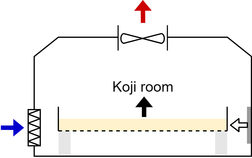
I hope this post will provide a bit of guidance to anyone trying to build a koji room (also known as the koji muro or sei-kiku shitsu), especially as they scale up to the 50-1500kg/batch range. I’ll go into the details of the history, design, and operation of the koji room.
This is part 2 of “How koji is produced on industrial scales”. (Click here for Part 1).
Introduction
As much as I enjoy learning about 50-ton capacity, fully automated koji making machines, these machines are expensive and fairly out-of-reach for smaller producers looking to enter the ‘micro-brewery’ scale.
That being said, koji rooms (koji muro) are still extremely commonplace. They have a fairly low capital cost, and many of the smaller koji-making machines are based inside of a koji room.
Although it appears to be a fairly simple piece of equipment, there’s a lot of interesting engineering that goes into a koji room. I couldn’t find any English guidance on the topic, but the key concept is essentially HVAC-meets-biology, with numbers and parameters from some key Japanese resources which I’ve cited at the end of this post.
I’ll be delving into the purpose of a koji room, some history, a design example, koji-making machines based within a koji room, and some of the finer details.
Design Requirements
A properly designed koji room must meet the following design criteria:
- Provide a work area that’s easy to sanitize
- Be insulated to prevent condensation
- Maintain a set temperature and humidity
- Be ventilated to remove heat, water, and carbon dioxide from koji growth
We’ll take a look at each of these in detail, and how they interact with each other. Firstly, a bit of history.
Traditional Koji Rooms (pre-1950s)
Breweries prior to the 1950s had virtually zero mechanization, and no modern materials of construction. During this time, four types of koji rooms were common: basement, half-basement, first floor, or upper floor - based simply on where they were constructed and the flow of material within the brewery.
In basement and half-basement koji rooms, steaming and soaking of the substrate would take place on the ground floor of the brewery and dropped into the koji room below. These rooms were typically lined with plaster, brick, or later concrete, typically in two layers and insulated with a mixture of rice straw and rice husks in-between.
First- and upper-floor koji rooms would also use rice straw and rice husks as insulation, lined between interior wooden (often cedar) walls and exterior walls.
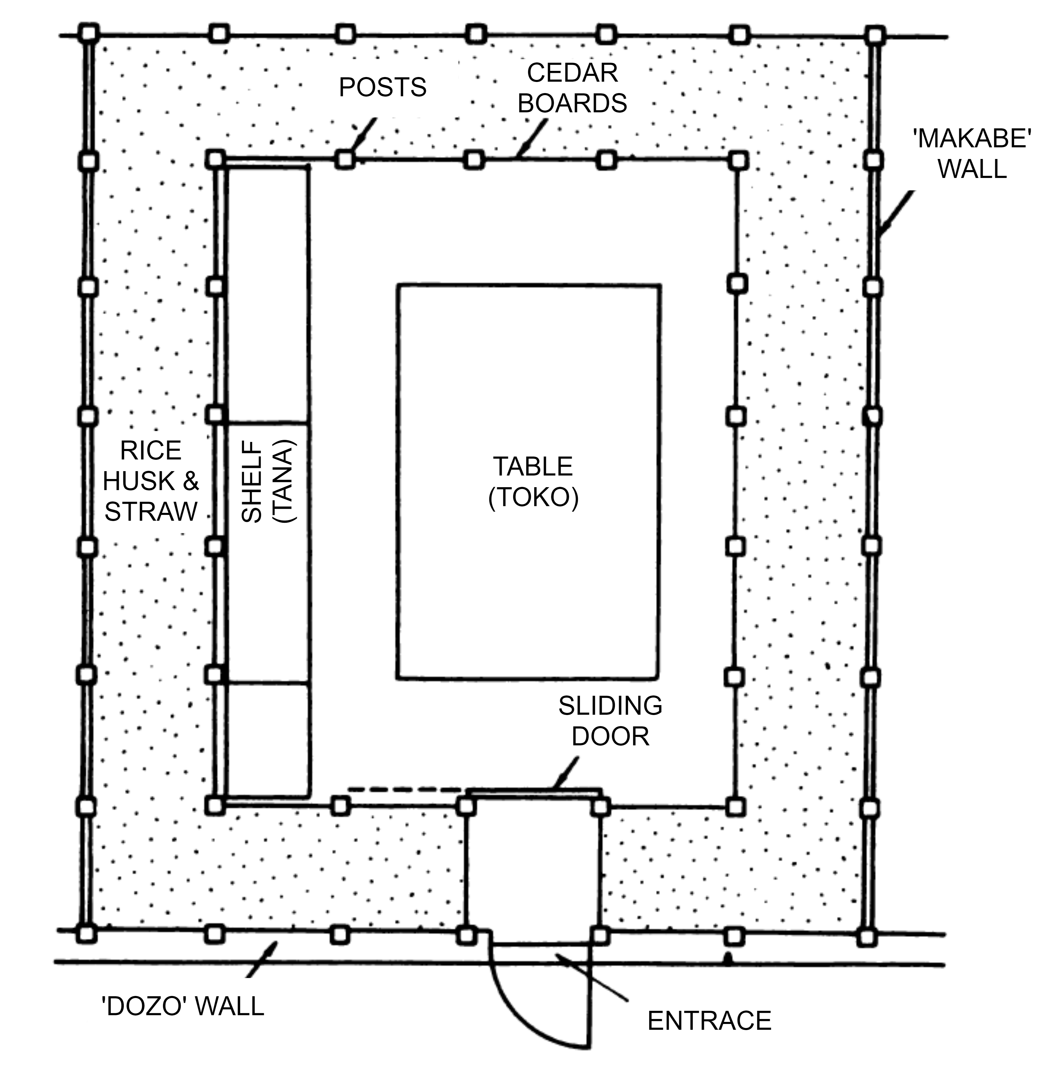 Plan view of a typical traditional first floor koji room (koji-muro) from [1]
Without any electric fans, these koji rooms were equipped with one or several pairs of chimneys called ten-mado. By using two chimneys set a different heights, hot moist air from the koji room would escape through the taller chimney and cold outdoor air would enter through the shorter chimney. This design employs a principle called the stack effect in HVAC. Operators could adjust a shutter at the bottom of the chimney to control air flow.
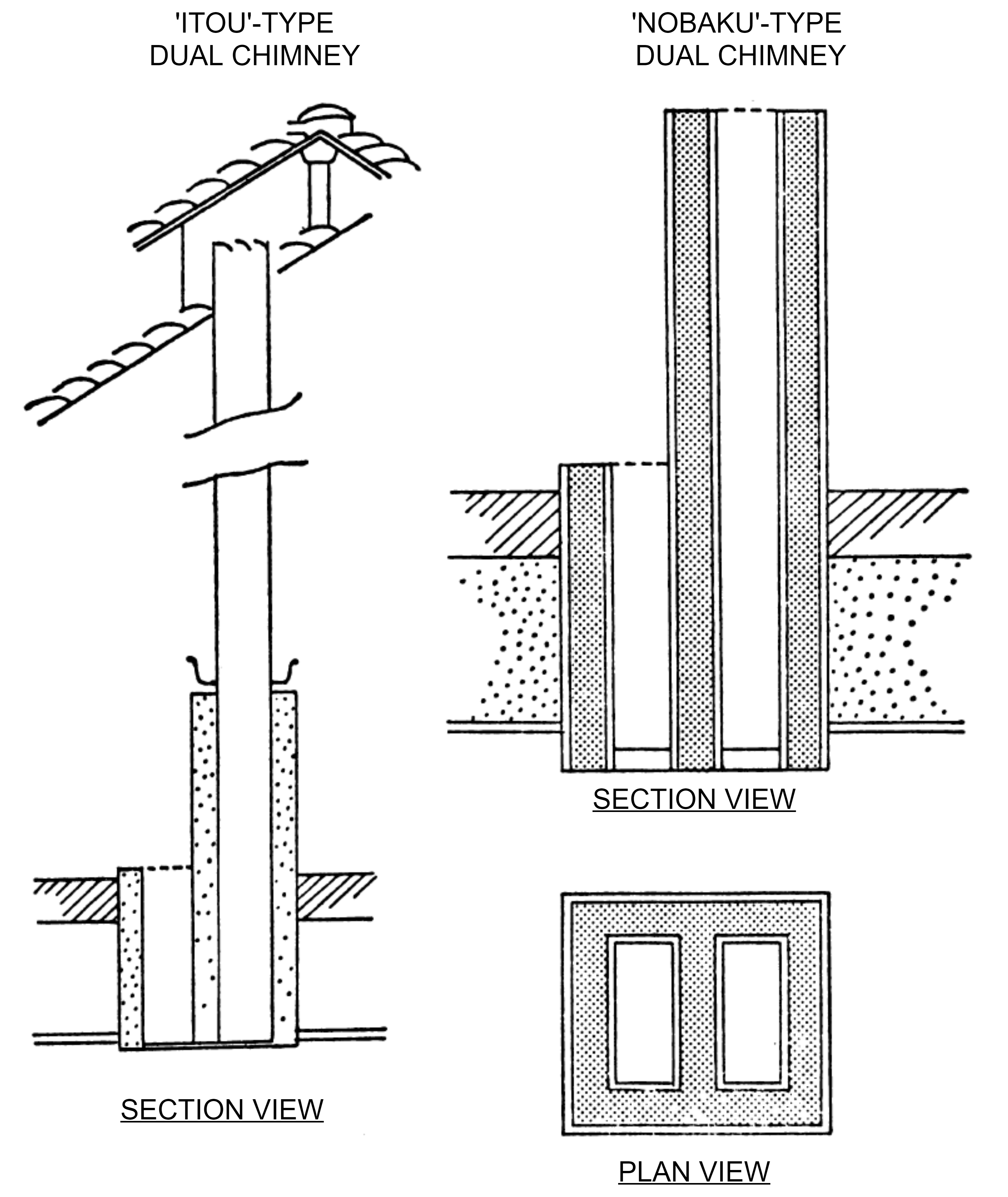 Two types of dual chimneys (ten-mado) from [2]
There were a few known issues with these older koji rooms. Firstly, they would often be heated by small fires or hot charcoals - and anoxia was a safety issue. Secondly, the rice straw insulation, although effective when dry, loses its thermal insulation properties when wet. They were also magnets for non-desirable organisms including Japan’s brewery enemy No. 1, Bacillus subtilis.
That being said, these koji rooms were effective - and even though they lack most modern HVAC luxuries, the brewery still had access to the two most important pieces of instrumentation: a dry-bulb and wet-bulb thermometer, from which you can calculate all properties of the room air using a psychrometric chart.
Modern Koji Rooms
Modern koji-rooms solved all the problems with old koji-rooms, and starting in the 1950s, all breweries quickly renovated to employ the following design features, which I’ll quickly summarize:
- Electric heaters (often wall-mounted panel heaters or wall-mounted heating coils)
- Modern insulation (fibreglass, mineral wool, PVC foam, styrofoam, or polyurethane foam)
- Modern materials of construction (coated steel, stainless steel)
- Exhaust fans and inlet louvres & dampers
- Humidifiers (often simple household humidifiers or misting nozzles)
Despite these upgrades, I’d like to point out that both cedar-lined interior walls and the dual-chimneys (ten-mado) are still commonplace in more traditional breweries - it seems these design elements have withstood the test of time.
Design of the Koji Room
Perhaps the easiest way to explain the design of a koji-room is to go through an example. I don’t want this blog post to become a textbook, so I’ll provide a quick overview of the design criteria first, and present the concepts visually. Anyone looking for calculation details can into to the Appendix at the very end of this post. A basic understanding of psychrometrics and heat transfer is nice to have for this exercise.
Let’s consider a koji room with the following parameters:
- Seishu (sake) rice-koji polished 75% with a capacity of 300kg steamed rice per batch (hiki-komi weight - more on the process here)
- Table koji method (more on methods here)
- Room conditions are 30°C at 70% Relative Humidity (RH) - constant throughout process
- Outdoor / brewery conditions are 5°C at 50% RH - sake brewing performed in the winter
When designing any equipment, we always consider the extreme cases under which it will operate, also known as the operating window. For this example, we’re considering operation on a cold day at two times: at the very start of the process immediately after inoculation (when the koji generates no heat) and at the peak of its growth (when the koji generates maximum heat output). This is a bit of an oversimplification, but it will be enough to demonstrate the concept.
Design basis
The table below provides all the key information needed to properly design a koji room (and a koji-making machine) for some well-known substrates:
Table 1 - Design parameters for common koji substrates [4]
| Substrate | Initial Moisture (%) |
Initial Specific Volume (L/kg) |
Peak Heat Generation (kJ/kg-dry/h) |
Total Heat Generation (kJ/kg-dry) |
|---|---|---|---|---|
| Wheat bran & rice husk koji (1:1) | 50-55 | 9.2 | 158 | 1990-2620 |
| Wheat bran koji | 50 | 4.4 | 138 | 1800-2100 |
| Miso rice koji (polishing ratio 90%) | 40-45 | 2.5 | 41.8-64.9 | 460-750 |
| Seishu rice koji (polishing ratio 75%) | 35 | 2.2 | 30 | 380-440 |
| Shoyu koji (soybean & wheat 1:1) | 40-45 | 2.9 | 130 | 1800-2300 |
With these parameters, the remainder of the process is fairly simple: all we have to do is go through four design calculations and determine, in order, the room dimensions, insulation, ventilation, and heating.
1. Dimensions
Let’s determine the size of our table (toko) and koji room. To fit 300kg of steamed rice for inoculation (tane-kiri) and at the end of the process (shimai shigoto) at a depth of 5cm, we need a 13.2 square meter table, housed in a koji room measuring about 8m(L) x 5m (W) x 2.2m(H) in order to fit clearances and other equipment (See Appendix - Step 1, Step 2).
2. Insulation
The koji room’s insulation must be sufficient to keep the room warm AND prevent condensation on the inside surfaces of the room. If we look at a section of the koji-room wall, overlaid with a steady-state temperature profile, it will look something like this:
![]() Depiction of 1-D steady state heat transfer through a wall
Depiction of 1-D steady state heat transfer through a wall
Our koji room, sitting at 30°C and 70% RH, will be slightly colder near the inside wall in an area known as the temperature boundary layer. The temperature right up against the interior wall must be greater than the dew point of the air in the koji room (at 30°C and 70% RH, the dew point is 23.9°C from a psychrometric chart) or condensation will form.
This is a 1-dimensional heat transfer problem. If we pick 4-inch polyurethane with a total RSI-value of 4.24 (RSI is the metric equivalent of the imperial R-value, a measure of an insulation’s thermal resistance), we can demonstrate that the wall temperature will not fall below 29.3°C. (see Appendix - Step 3). This might seem like overkill - our design requirement was 23.9°C! But trust me, insulation is cheap relative to the rest of the room; and the heat retention will save costs in the long run.
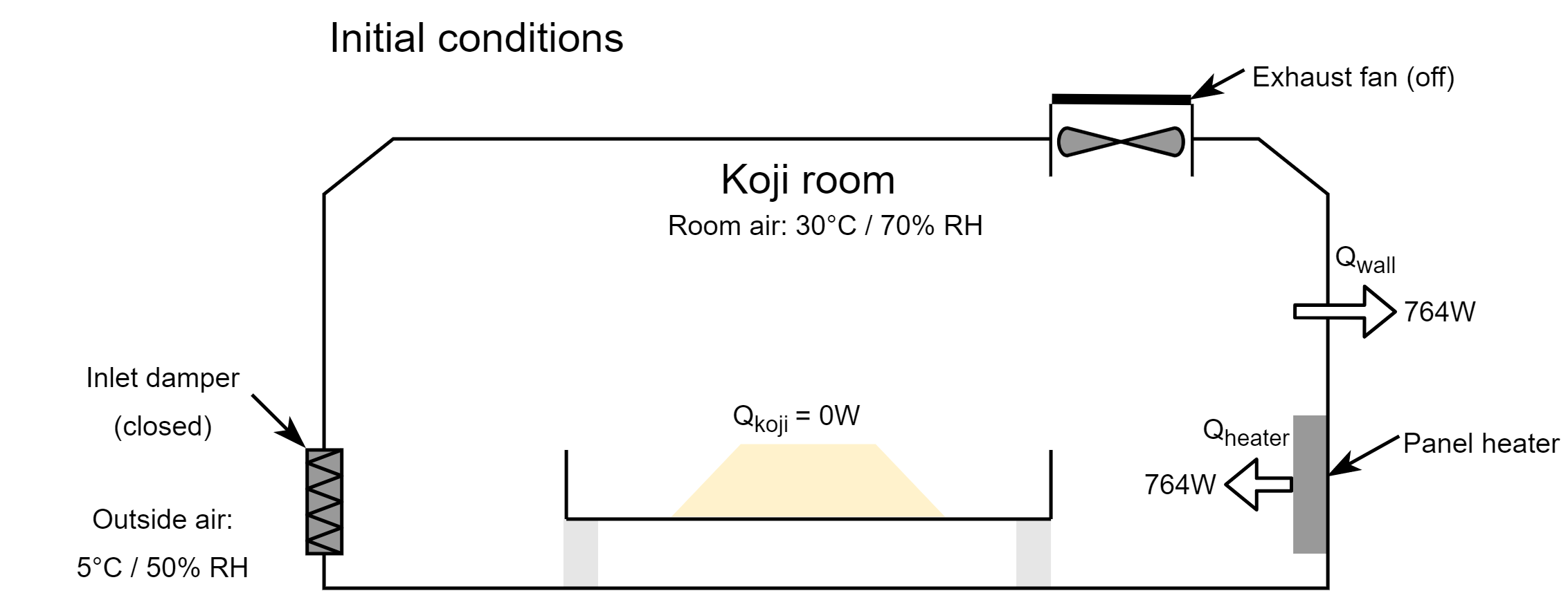
If the indoor conditions are maintained at 30°C, we can further demonstrate that the heat losses through the wall will total 764W. To keep the room warm, an equal amount of heat must be supplied. Let’s illustrate the conditions of the koji room at time t=0 after inoculation, during which the koji generates no heat and all openings to the room are closed:
3. Ventilation
The koji room’s ventilation must be sufficient to remove excess heat, humidity, and water generated by the koji as it grows. Removal of water vapour is usually the limiting design criteria, and requires a greater volume of ventilation than heat removal or carbon dioxide removal.
Let’s demonstrate which of these three design criteria is our limit, using our example.
First, consider the requirements for heat removal. We can show that our 300kg of rice-koji at hiki-komi has a dry weight of 195kg, and will generate 1623W at the peak of its metabolism (see Appendix - Step 4). Our conductive heat losses were calculated to be 764W, so we know that ventilation for heat removal must equal 859W by exchanging indoor air with cold, outdoor air. This requires a ventilation rate of 41m³/h.

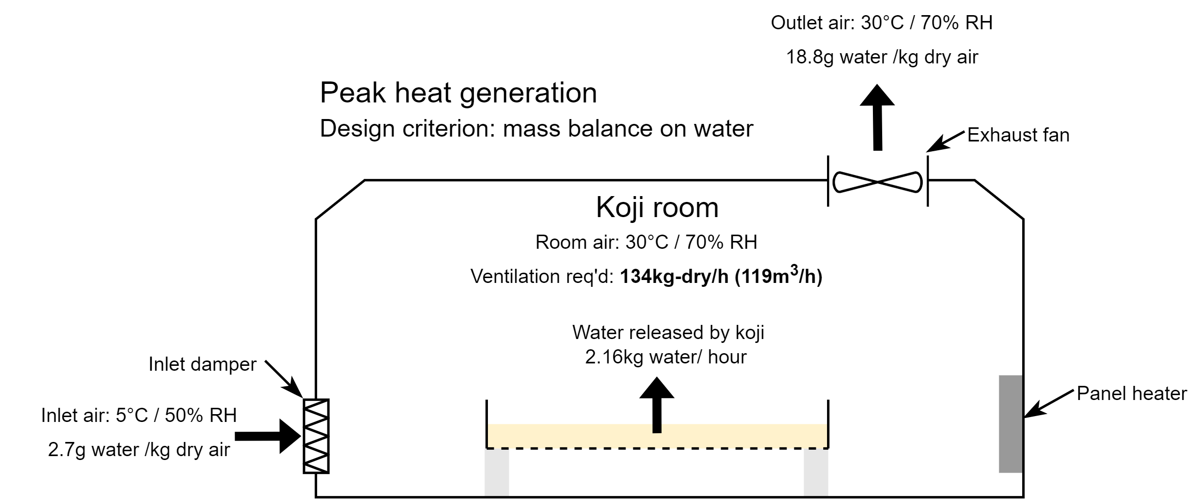
Next, let’s consider the requirements for moisture removal. About 80% of the heat generated by koji is lost as water vapour, with the remaining 20% lost due to other effects. At the peak of its heat generation, we can show that the our 300kg of koji will emit 2.16kg of water per hour (see Appendix - Step 5). By exchanging moist indoor air with dry, outdoor air, we can show that a ventilation rate of 119m³/h is necessary to remove the moisture emitted by koji.
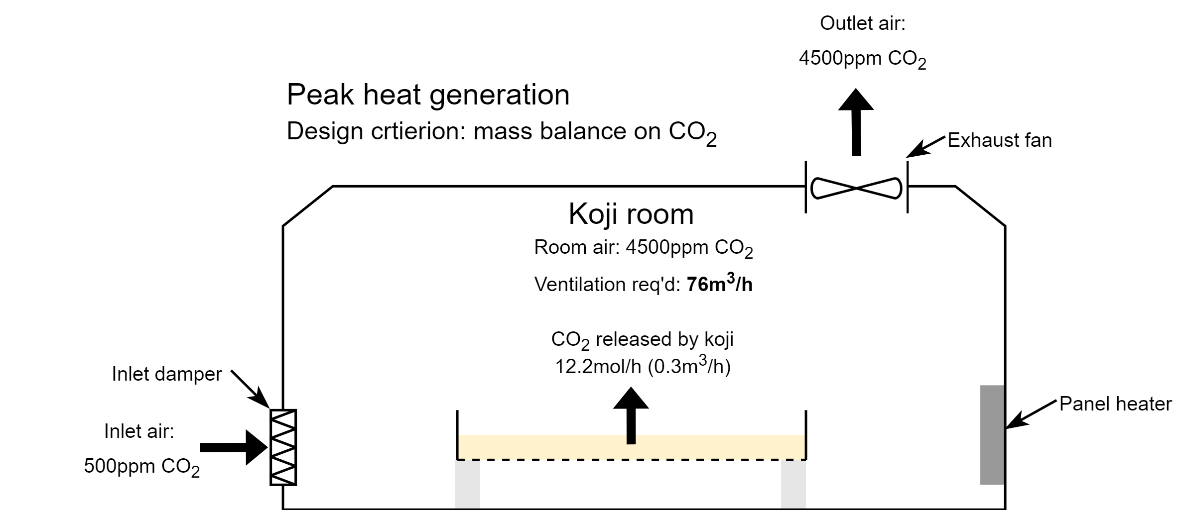
Finally, let’s consider the requirements for carbon dioxide removal. Koji has a respiratory coefficient of around 1.0 throughout its entire process, which means that the koji’s peak heat generation of 1623W equates to a CO₂ generation rate of 0.3m³ CO₂/h (see Appendix - Step 6) using the aerobic metabolism equation:
\[C_6H_{12}O_6+6O_2 \rightarrow 6CO_2 +6H_2O+2872kJ/\text{mol} \cdot \text{glucose}\]If we maintain an indoor carbon dioxide concentration at 4500ppm, which is 500ppm below the OSHA Permissible Exposure Limit (PEL = 5000ppm), and assume an outdoor CO₂ concentration of 500ppm, we can show that the flow rate necessary to remove all generated carbon dioxide is 76m³/h.
Comparing the three ventilation rates, we can see that moisture removal, at 119m³/h, is the limiting design criteria in our scenario.
4. Heating
Knowing that our maximum ventilation rate will be 119m³/h, let’s size the heating panels of the koji-room. Our conductive heat losses are 764W, and ventilating fresh air at 119m³/h removes 2480W of heat. Our koji generates 1623W of heat at its peak, so our heater must provide at least 1621W of heat (see Appendix - Step 7):
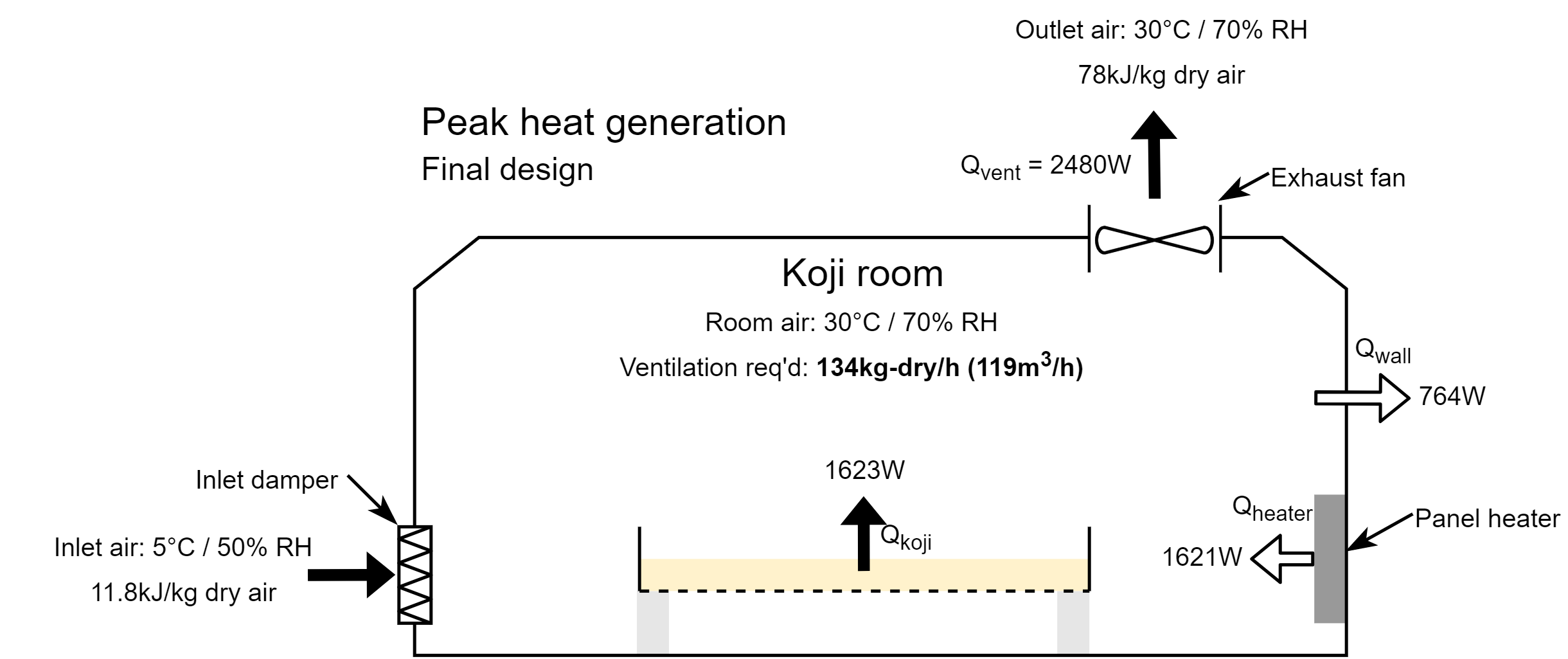
And that’s it! At t=0h, our heaters will be running at 764W and our ventilation turned off; and at the peak of growth, our heaters will be running at 1459W and our ventilation at 119m³/h. This is our operating window, and every other point in time will fall somewhere between these two extremes. Achieving steady conditions is the job of whatever control system we select. This can range from a basic thermostat and humidistat to a programmable controller.
Design Notes
Engineering is all about precise calculations, then applying a bunch of somewhat arbitrary safety factors, gut intuition, and hoping your control system is tuned well enough. In the example above, I would install an exhaust fan capable of 150m³/h, and heater of 2000W, depending on what’s available from the vendor.
One interesting observation is that, since moisture removal is the limiting factor during the peak of koji growth, we can demonstrate that humidification is not required during koji-making except for the initial stages (by the same logic, if heat removal was the limiting factor, we would not require any heating and would have to supplement humidity).
You might also notice that, if outdoor conditions approach the conditions of the koji room, the ventilation requirements would approach infinity. If it must be done in summer conditions, air conditioning and/or dehumidification is sometimes necessary - but that’s enough calculations for one post.
Ventilation requirements for CO₂ removal are also inversely proportional to the concentration of CO₂ you’d like to maintain in the room. That’s why we want to pick the highest CO₂ concentration safely possible (5000ppm - 500ppm contingency = 4500ppm) to reduce ventilation requirements for CO₂ removal.
Finally, the example above considers 300kg of steamed rice going through the entire growth cycle in one room. It’s common to have two batches going simultaneously in one room, one in the first phase of growth, on the table (toko-momi to mori) and one in the latter stage of growth, on another table; or in trays or boxes placed on shelves (tana) along the perimeter (mori to dekoji). It’s also common to perform the process in multiple, adjacent rooms so they can be controlled separately. These will all affect the final design.
Procurement
Great, so how do I actually build a koji room?
The best approach is to procure a walk-in cooler with the correct specifications and add the necessary retrofits (exhaust fan, intake damper, heating panels) through an experienced HVAC contractor. Because these are common (and sometimes prefabricated) structures, they are easy to find, relatively inexpensive, and easy to accommodate custom specifications. Since they’re used in food settings, they’ll likely be complaint with local food safety regulations and easy to clean. From what I can tell, many modern koji-rooms in Japan are no more than modified walk-in coolers.
A few general notes when procuring a koji room:
- Make sure to follow your local building code, health and safety codes, food safety codes, sanitation practices, fire safety codes, and electrical codes.
- The exhaust duct of any koji room is prone to condensation. If this drips onto the koji, you’ll have a problem. Heating the duct, or installing heat-trace, is recommended.
- Provide room to store cloth, fabrics, and to hang koji-related equipment
- Stainless steel panel heaters are best practice - installed close to the floor of the koji room
- A simple household humidifier or atomizing nozzle is sufficient for humidification
To date, I could only find one specialty fabricator of traditional koji rooms; a company called Nitto Kogyosho Co., Ltd. based out of Tochigi, Japan. They still use Akita cedar to build them, with dual chimneys or fans for ventilation.
Machines based inside the koji room
Many smaller koji-making machines are simply based in a koji room. These machines are simple, and use a blower that sends air intermittently through the bed of koji, controlled by a temperature probe embedded in the koji itself. Every time the koji gets too warm, the blower turns on until the temperature is sufficiently lowered, and repeat. This keeps the koji within a fairly narrow range of temperatures.
However, the blower must operate intermittently - otherwise the entire bed of koji will quickly dry out. More advanced machines like the tent-type machine (ten-maku shiki) recirculate a portion of the air leaving the koji layer to mitigate this drying effect.
Here’s an example of the tent-type koji-making machine:
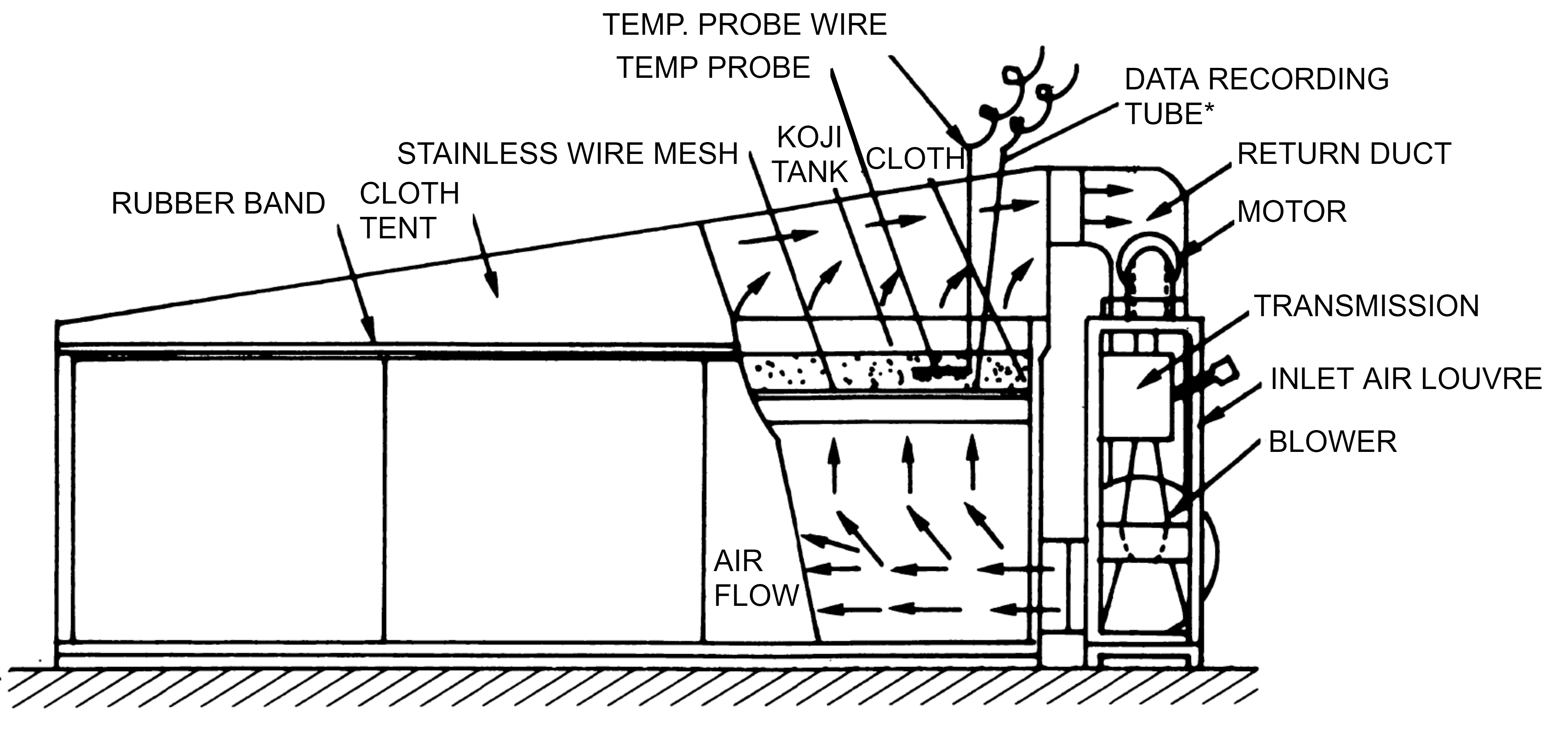
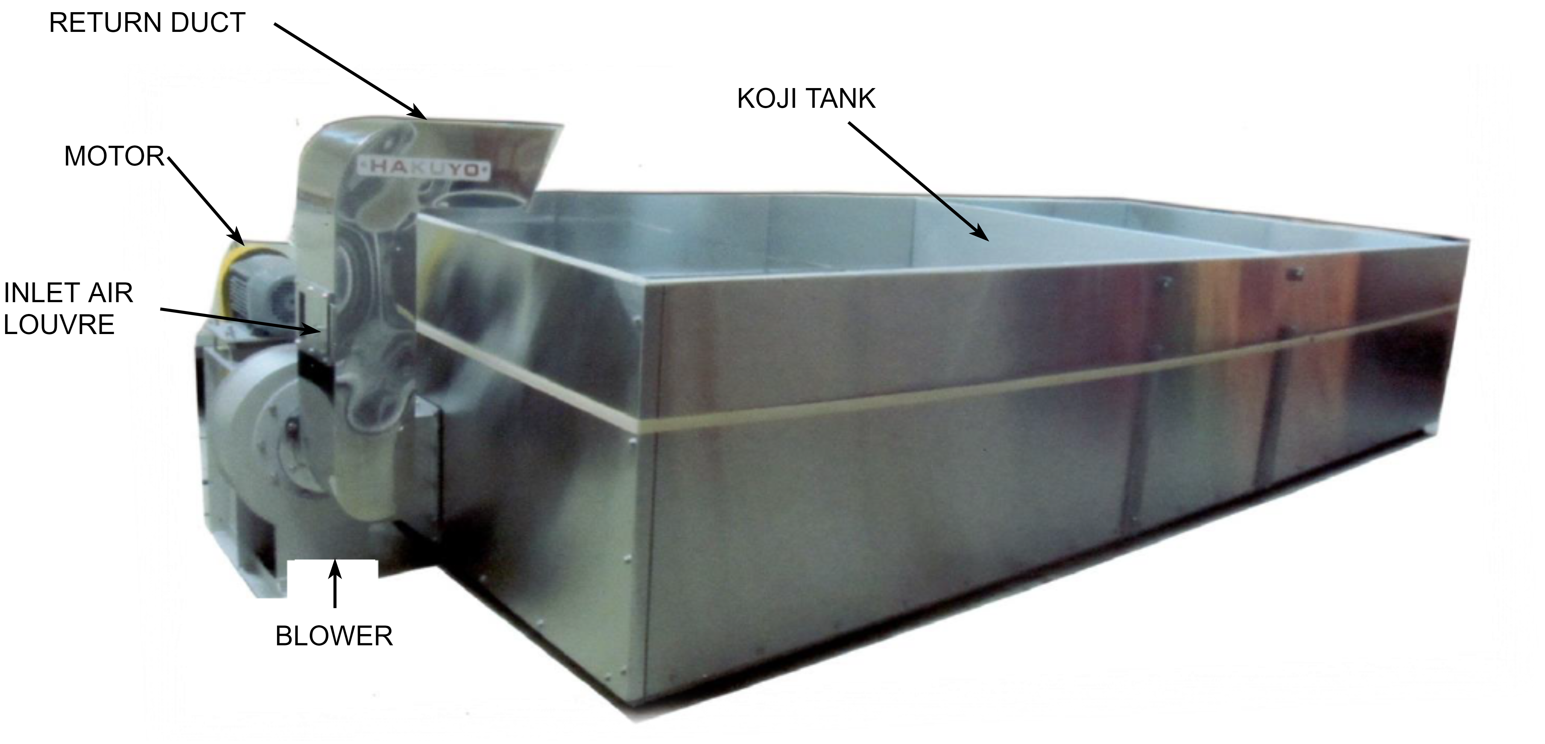
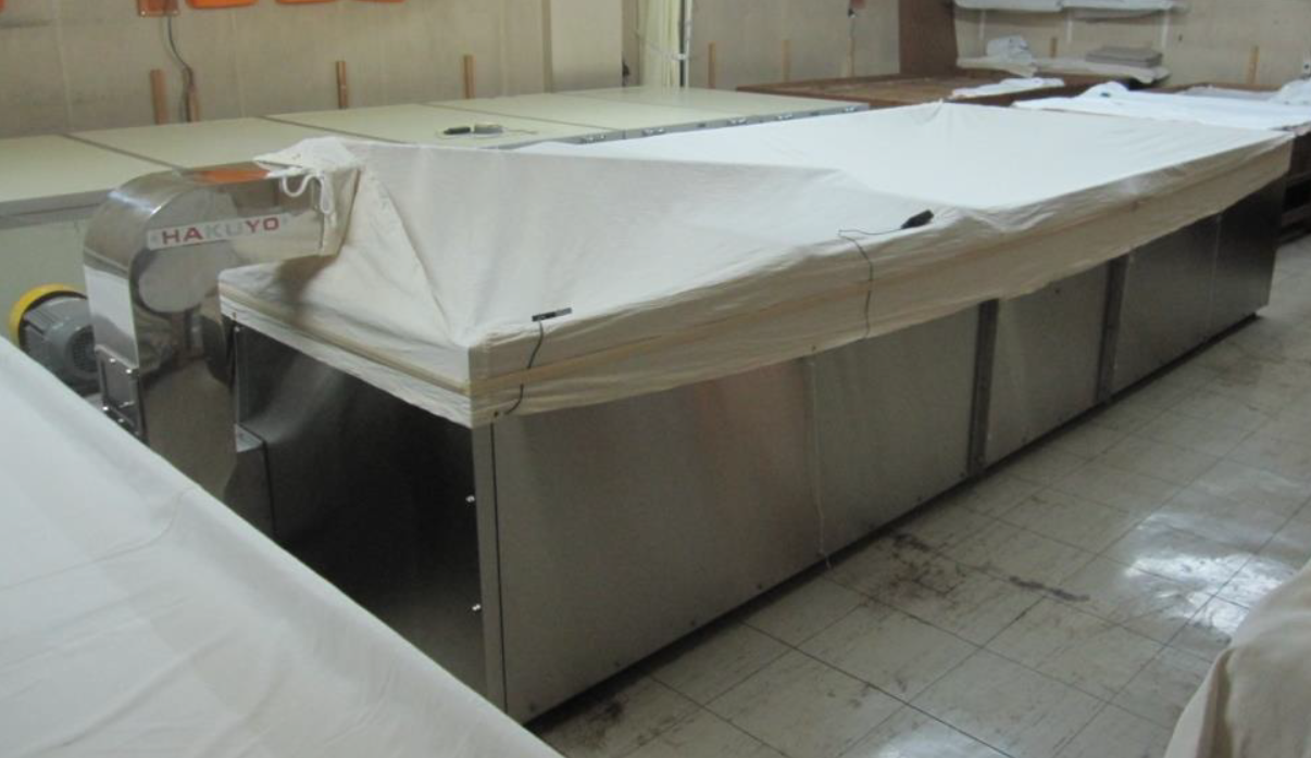 Top to bottom: tent-type koji machine schematic, with the cloth tent removed, and with the cloth tent attached - from Hakuyo Co., Ltd.
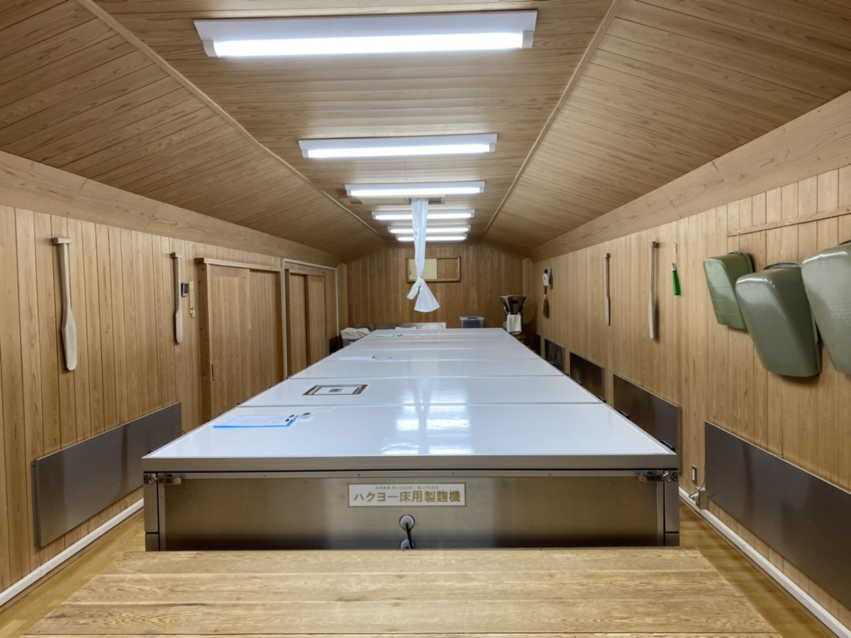
Here’s a simpler box-type koji-making machine, which does not recirculate any air:
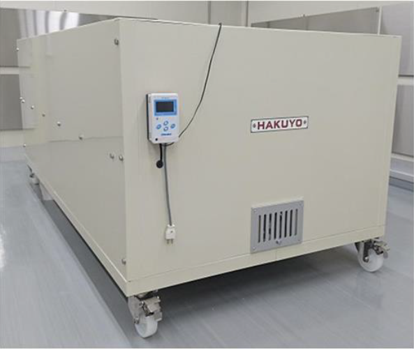 A box-type koji-making machine situated in a koji room - from Hakuyo Co., Ltd.
There are also unventilated type machines, such as Fujiwara’s VEX-type machine which simply uses a thin layer of koji and a semi-permeable ePTFE membrane to control moisture removal.
While it may be difficult procure Japanese koji-making equipment overseas, you can look at their product catalogue sheets to get a feel of how they’re designed, their capacities, and the size of the blower.
Some other equipment worth mentioning, primarily used to reduce labour costs:
Air shooter
A common way to transfer steamed substrate into the koji room, and finished koji out of the room, is to use a device called an air shooter. This is a Japanese wasei-eigo term for what would commonly be called a pneumatic conveying system consisting of: 1) a blower 2) a feed assembly consisting of a hopper, rotary valve, and solids-conveying educator, 3) a bunch of hose, and 4) an outlet cyclone (optional). These are much faster than transferring substrate by hand.
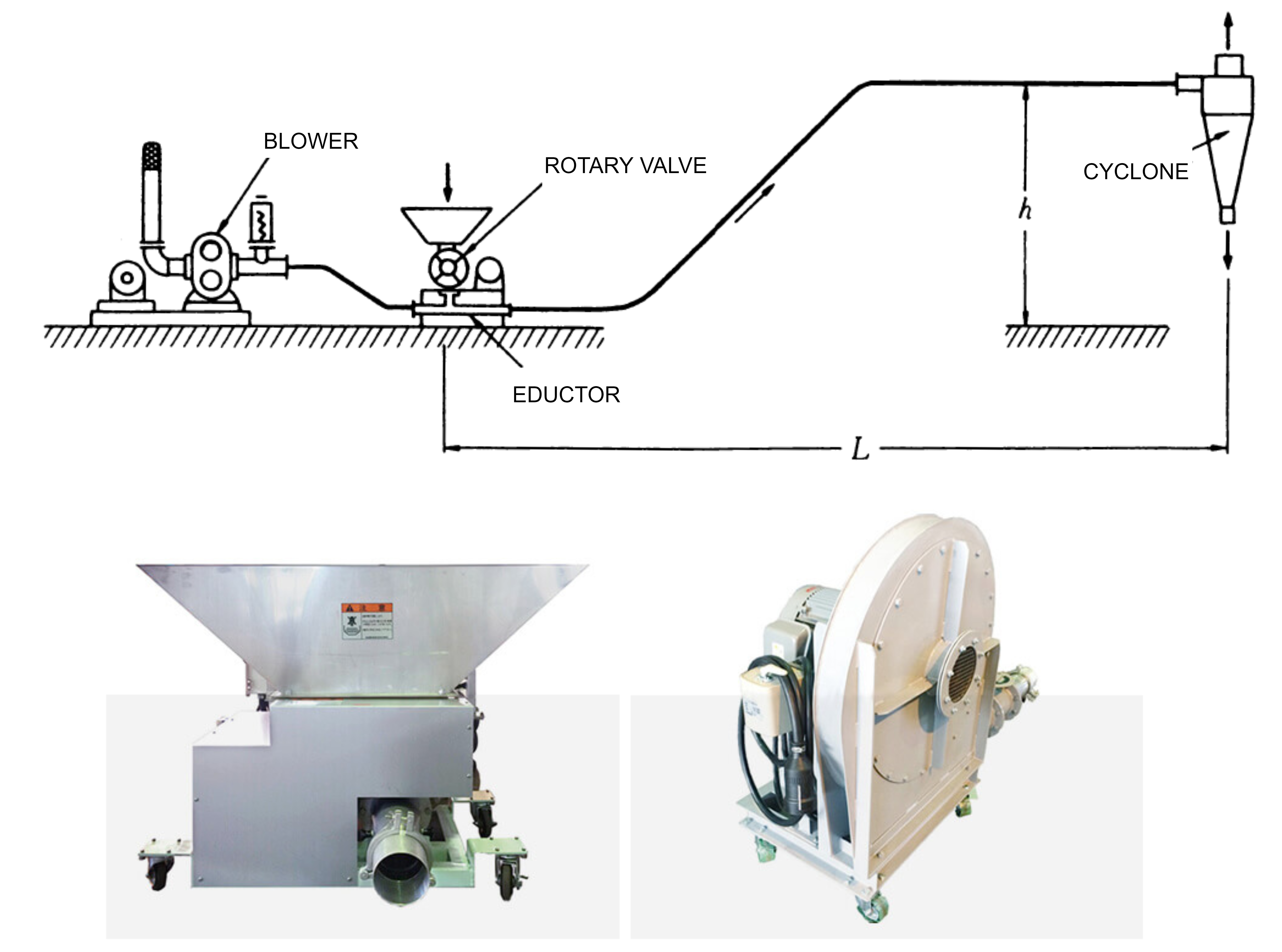 Top: a schematic of an air-shooter (pneumatic conveying system), bottom-left: feed assembly, bottom-right: blower. From [1] and Toyo Shokai Co., Ltd.
Mixing (kiri-kaeshi) machine
A quicker way of performing koji mixing is with a mixing (kiri-kaeshi) machine. This is nothing then a solids mixer with a mesh screen for breaking up clumps.
![]() A mixing (kiri-kaeshi) machine, from Hakuyo Co., Ltd.
A mixing (kiri-kaeshi) machine, from Hakuyo Co., Ltd.
Load cells
Some breweries install load cells at the feet of their koji-making table to track substrate weight throughout the process.
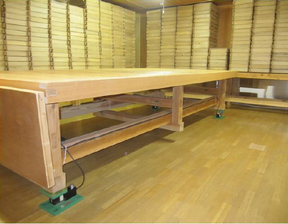 A load cell installed underneath a table (toko) in a traditional style room, from Hakuyo Co., Ltd.
The room
And finally here’s the best picture I could find of a koji room online, which is cedar-lined, uses a modern koji-making machine, and includes wall-mounted panel heaters, a mixing machine, and some other features discussed in this post.
 A photo of koji room from www.sake-hourai.co.jp: with heating panels (lower side of walls), a room-based koji machine (centre), kiri-kaeshi machine (back of room), thermometer and wet-bulb thermometer (left) and exhaust chimney (roof)
Conclusions
There are a lot more details difficult to cover in one post, but hopefully this will give you an idea of how to size, construct, and operate a koji room (koji muro), and even how to build some of the simpler koji-making machines.
If you plan on constructing a koji room, or have constructed one already, I’d love to hear about it! Feel free to reach out to me on twitter @Keeifa
This post is part of an ongoing effort to translate Japanese koji-related literature to the west. If you’re interested in this, feel free to reach out to me as well.
In the next post of this series, we’ll look at fully automatic koji making machines.
References
- Shochu Manufacturing Technology, 3rd ed.; Nishitani, N.; The Brewing Society of Japan: Tokyo, 2014
- Koji Studies, 6th ed.; Hideya, M.; The Brewing Society of Japan: Tokyo, 2018.
- Sato, K. Solid-State Culture (I) Characteristics and the Application of Solid-State Culture. Journal of the Brewing Society of Japan 1992, 87 (8), 558–565. https://doi.org/10.6013/jbrewsocjapan1988.87.558.
- Sato, K. Solid-State Culture (II) Controlling of Growth of Microorganism on Solid Media. Journal of the Brewing Society of Japan 1992, 87 (12), 874–879. https://doi.org/10.6013/jbrewsocjapan1988.87.874.
- Sato, K. Solid-State Culture (III) Characteristics of Solid-State Fermentors and the Applications. Journal of the Brewing Society of Japan 1993, 88 (10), 763–774. https://doi.org/10.6013/jbrewsocjapan1988.88.763
- Nagatani, M. Koji Machinery Equipment Design Method (Part 1). Journal of the Brewing Society of Japan 1979, 74 (9), 593–595. https://doi.org/10.6013/jbrewsocjapan1915.74.593.
- Nagatani, M. Koji Machinery Equipment Design Method (Part 2). Journal of the Brewing Society of Japan 1979, 74 (10), 653–655. https://doi.org/10.6013/jbrewsocjapan1915.74.653.
- Nagatani, M. Koji Machinery Equipment Design Method (Part 3). Journal of the Brewing Society of Japan 1979, 74 (12), 813–815. https://doi.org/10.6013/jbrewsocjapan1915.74.813.
Appendix
Here are the calculations for the example in this post. This will read like an engineering textbook.
Step 1 - Determine the room and outdoor conditions
The design basis will be for a koji room with the following conditions:
- Steamed seishu rice, polished 75%, 300kg steamed rice per batch, single room and one batch per room
- Sea level (101.3kPa)
- Indoor conditions - 30°C / 70% RH. From a psychrometric chart, the indoor air has the following conditions:
- Enthalpy: 78.25kJ/kg dry air
- Absolute humidity: 18.8 g water / kg dry air
- Specific volume: 0.885 m³/kg dry air
- Outdoor conditions - 5°C / 50% RH - constant throughout the process
- Enthalpy: 11.78kJ/kg dry air
- Absolute humidity: 2.7 g water / kg dry air
- Specific volume: 0.792 m³/kg dry air
Air flows in this post are using a dry air basis at 30°C / 70% RH (indoor conditions).
Step 2 - Determine the koji amount, dry weight, and room dimensions.
The weight of steamed rice at inoculation (hiki-komi) will be 300kg. If the unsoaked white rice has a moisture of 13%, and the water absorption ratio at inoculation is 34%, the actual water content of the koji is:
\[\%Total\ moisture = \frac{Total\ Water}{Total\ Weight}=\frac{13\%+34\%}{100\%+34\%} = 35.1\%\]This is in agreement with Table 1. Thus the dry weight of the steamed rice is 194.8kg and its peak heat generation is 5843kJ/h or 1623W (unit conversions not shown).
Let the depth of koji be 5cm. Based on Table 1, 300kg of steamed rice will occupy approximately 660L or 0.66m³ in volume and require a table with an area of 13.2 square meters (geometric calculations not shown). Let’s select a 5.3m x 2.5m table. To allow for clearance and the storage of other items, let’s select a room of 8m (L) x 5m (W). Finally, a ceiling height of 2.0-2.2m is standard - we will select 2.2m (H).
Step 3 - Determine heat loss through the room walls, and check for condensation
1-D steady state heat transfer through a wall is given by the following equation: \(Q=UA(T_1-T_2)\) Where,
- Q = Heat loss (W)
- A = Area (m)
- U = Overall heat transfer coefficient (W/m-K )
- T₁ = Bulk koji room temperature
- T₂ = Bulk outdoor temperature
The overall heat transfer coefficient is given by the following equations (the first equation uses thermal conductivity, and the second equation uses R-values, which are often more convenient):
\(\frac{1}{U} = \frac{1}{h_1}+\sum\frac{x_n}{k_n}+\frac{1}{h_2} \\ \frac{1}{U} = \frac{1}{h_1}+\sum RSI_n +\frac{1}{h_2}\) Where,
- $h_1$ = convective heat transfer coefficient (inside room) (W/m-K )
- $h_2$ = convective heat transfer coefficient (outside room) (W/m-K )
- $x_n$ = thickness of insulation layer (m)
- $k_n$ = thermal resistance of insulation layer (W/m-K )
- $RSI_n$ = insulation R value (metric RSI value), equivalent to x/k (m-K/W)
Select a 4-inch polyurethane insulation with a total metric RSI value of 4.24 (m-K/W). We’ll use a convective heat transfer coefficient of 8.0 W/m-K on both sides of the wall. Now, we can find the overall heat transfer coefficient:
\[\frac{1}{U} = \frac{1}{8}+4.24 +\frac{1}{8} \text{ (SI Units)}\\ U = 1.3W/m^2\cdot K\]As well as the heat losses through the wall:
\[Q = (1.3W/m^2\cdot K)(137.2m^2 )(30^\circ C-5^\circ C) \\ Q = 764W\]Heat flux is simply heat transfer divided by area, or Q/A. In 1-D steady state heat transfer, this term is constant no matter where you are along the wall. \(\frac{Q}{A} = h(T_1 - T_w)\) Where,
$T_w$ is the temperature at the koji room wall
If we solve for the wall temperature:
\[763W = (8W/m^2\cdot K)(137.2m^2)(30^\circ C-T_w)\\ T_w = 29.3^\circ C\]This is well above the dew point of our koji room, so no condensation is expected.
Step 4 - Determine the ventilation requirements for heat removal
This is a heat balance on the koji room:
\[Q_{koji} = Q_{wall} + Q_{vent}\]Where,
- $Q_{koji}$ - peat heat generation from koji (W)
- $Q_{wall}$ - heat losses through the wall (W) (from Step 3)
- $Q_{vent}$ - heat removed via ventilation (W)
Heat removed by ventilation is simply flow rate times the difference in the air enthalpy in and out of the system:
\[Q_{vent} = \dot{m}(H_1 -H_2)\]Where,
- ṁ = mass flow rate of air (kg dry air/s)
- H₁ = enthalpy of air leaving the koji room (kJ/kg dry air)
- H₂ = enthalpy of air entering the koji room (kJ/kg dry air)
Our heat balance becomes:
\[Q_{koji} = Q_{wall} + \dot{m}(H_1-H_2)\\ 1623W = 878W + \dot{m}(78.3kJ/kg - 11.78kJ/kg)\cdot(\frac{1000W}{kJ/s})\\ \dot{m}=0.130 kg\ dry\ air/s\]We know its specific volume is 0.885 m³/kg dry air so the ventilation rate is 0.0114m³/s or 41.1m³/h (indoor basis).
Step 5 - Determine the ventilation requirements for moisture removal
Mass balance on water: \(\text{Water generated by koji} = \text{Water removed by ventilation} \\ \frac{FQ_{koji}}{\Delta H_{vap,T_1}}=\dot{m}(W_1-W_2)\)
Where
- F = fraction of heat generated by koji removed by evaporative cooling (0.8)
- $ΔH_{vap,T1}$ = heat of vaporization of water at conditions T₁ inside koji room (J/g water)
- W₁ = koji room absolute humidity (g water / kg dry air)
- W₂ = outdoor absolute humidity (g water / kg dry air )
Our mass balance becomes:
\[\frac{(0.8)(1623W)}{2429.8J/g} = \dot{m}(18.8\text{g water/kg dry air} - 2.7\text{g water/kg dry air}) \\ m = 0.03317\text{kg dry air/s}\]We know its specific volume is 0.885 m³/kg dry air so the ventilation rate is 105.7m³/h (indoor basis).
Step 6 - Determine the ventilation requirements for CO₂ removal
Conversion of aerobic metabolic heat generation to carbon dioxide generation:
\[\begin{align} & C_6H_{12}O_6+6O_2 \rightarrow 6CO_2 +6H_2O+2872kJ/\text{mol} \cdot \text{glucose} \\ & 2872kJ/\text{mol}\ \text{glucose} \times\frac{1 \text{mol}\ \text{glucose}}{6\text{mol} \ CO_2}= 478.7kJ/\text{mol}\ CO_2 \rightarrow0.00209\text{mol}\ CO_2 /kJ \\ & \frac{0.00209\text{mol}\ CO_2 }{kJ}\times \frac{5843kJ}{h}(Q_{koji})=12.2\text{mol}\ CO_2 /h \end{align}\]We can convert to volumetric CO₂ generation using the ideal gas law:
\[\dot{V}_{CO_2,koji}=\frac{\dot{n}RT}{P}\\ \dot{V}_{CO_2,koji} =12.2\text{mol}\ CO_2 /h\times\frac{(8.314J\text{mol}^{-1}K^{-1})(303.15K)}{101300Pa} \\ \dot{V}_{CO_2,koji} = 0.304m^3/h\]Mass balance on carbon dioxide:
\[CO_2 \text{ generated by koji} = CO_2 \text{ removed by ventilation} \\ \dot{V}_{CO_2,koji} =\dot{V}(C_1-C_2)\]Where,
- $m_{CO₂,koji}$ = CO₂ generated by koji (m³/h)
- V(dot) = ventilation flow rate (m³/h)
- C₁ = concentration of CO₂ inside koji room (fraction)
- C₂ = concentration of CO₂ outside (fraction)
Our mass balance becomes:
\[0.304m^3/h = \dot{V}(0.004500-0.000500) \\ \dot{V}=75.9m^3/h\]Step 7 - Determine the heating requirements
Heat balance on the koji room:
\[Q_{koji}+Q_{heater}=Q_{wall}+Q_{vent}\]Where $Q_{heater}$ = heat required by the heater
Our heat balance becomes:
\[1623W + Q_{heater} =763W + (0.03317kg\ \text{dry air}/s)(78.3kJ/kg - 11.78kJ/kg)\cdot(\frac{1000W}{kJ/s}) \\ Q_{heater} = 1621W\]